My name is Kevin, and at Dongxin Electronic Technology, my world revolves around precision on a microscopic scale. I’ve had the privilege of working with engineers like Marcus in Germany—professionals who understand that the reliability of a multi-million-dollar production line can hinge on the integrity of a single, hair-thin wire. This wire forms a bond, an electrical and mechanical connection so critical that it underpins nearly every modern electronic device. This is the world of the wire bond. It's a technology far more sophisticated than simple solder, and mastering it is essential for anyone in our field. In this guide, we will dissect the wire bond, exploring the science, the methods, and the materials that create these vital connections, providing you with the deep technical insights needed to perfect your own bonding processes.
What is the Fundamental Purpose of Wire Bonding in an Electronic Device?
The primary purpose of wire bonding is to make electrical connections. Specifically, wire bonding is the process of connecting a microscopic integrated circuit, or chip, to its packaging or to a printed circuit board. This bond is the essential communication link. Without it, the powerful processing capabilities of the chip would remain isolated and useless. Wire bonding provides a flexible, reliable, and cost-effective method to create these crucial interconnects. Every wire acts as a tiny bridge, carrying power into the chip and data out of it. A single, complex electronic component might contain hundreds, or even thousands, of these individual bond wires.
The wire bond itself is a solid-state weld. Unlike other methods that involve melting materials, wire bonding uses a combination of force, temperature, and ultrasonic energy to create a direct atomic bond between the wire and a metal pad on the chip (the bond pad). This creates an incredibly robust connection. A good bond has excellent electrical conductivity and mechanical strength, ensuring the electronic device functions reliably over its entire lifespan. The intricate network of these bond connections forms the backbone of modern electronics, from the smartphone in your pocket to the advanced control systems in an electric vehicle. The quality of each bond directly impacts the performance and longevity of the final product.
The importance of a good wire bond cannot be overstated. A single faulty bond can cause an entire system to fail. Therefore, creating a perfect bond every time is the ultimate goal. This requires a deep understanding of the materials involved, the physics of the bonding processes, and precise control over the machinery. The wire itself, the bond pad metallization, and the bonding parameters must all work in harmony. This is why the wire bond is a focal point for process engineers striving for zero-defect manufacturing. Every successful bond is a testament to the precision of the technology.
How Does a Wire Bond Differ from a Solder Connection?
While both a wire bond and a solder joint create electrical connections, they are fundamentally different processes with distinct applications. The most significant difference is that wire bonding is a solid-state process that creates a direct metallurgical bond, whereas soldering is a process that uses a filler material (solder) with a low melting point to join two surfaces. Think of a wire bond as a microscopic weld and solder as a metallic glue.
Solder works by melting and flowing between the components to be joined. When it cools, it solidifies, creating both a mechanical bond and an electrical path. This process is ideal for connecting larger electronic components to circuit boards. However, the heat required for solder can damage a delicate semiconductor chip. Furthermore, solder joints are typically much larger and less precise than a wire bond. You simply cannot use solder to create the thousands of microscopic connections required on a modern chip.
In contrast, a wire bond is formed without melting the wire or the bond pad. The ultrasonic energy and pressure cause the atoms of the wire and the pad to diffuse into one another, forming a single, continuous metallic structure. This direct bonding method creates a stronger, more reliable, and much smaller connection. The process is also much faster on a micro-scale. While solder is perfect for board-level assembly, the wire bond is the dominant technology for chip-level interconnection. A wire bond is a far more intricate and precise bond than a solder connection.
What are the Three Types of Wire Bonding Processes Used Today?
In the world of microelectronics, there are three types of wire bonding that dominate manufacturing: thermosonic bonding, ultrasonic bonding, and thermocompression bonding. Each method of wire bonding offers a unique combination of heat, pressure, and energy to create a reliable bond. Understanding these bonding techniques is essential for selecting the right process for a specific application.
-
Thermosonic Bonding: This is by far the most common type of wire bonding used today, especially for gold wire bonding and copper wire bonding. It combines all three elements: heat, force, and ultrasonic energy. The substrate is heated to a moderate temperature (typically 125-150°C), which softens the materials slightly and makes them more receptive to bonding. The bonding tool then presses the wire onto the bond pad while applying ultrasonic vibrations. This combination allows for a very fast and reliable bond at lower temperatures and forces than thermocompression, protecting the delicate chip.
-
Ultrasonic Bonding: This bonding method is often called "cold" bonding because it is typically performed at room temperature. It relies almost exclusively on ultrasonic energy and pressure to create the bond. The high-frequency scrubbing action of the tool against the wire breaks down surface oxides and creates the friction necessary for a solid-state weld. Ultrasonic bonding is the standard method for aluminum wire bonding, as aluminum surfaces readily form a tough oxide layer that needs to be scrubbed away. The lack of external heat makes this process ideal for temperature-sensitive devices.
-
Thermocompression Bonding: This is the original wire bonding technique. It relies solely on high heat (over 300°C) and pressure to form a bond. The wire and bond pad are heated to a point where their atoms are mobile enough to diffuse and form a bond when pressed together. While effective, the high temperatures can damage or degrade the semiconductor chip. As a result, this method is less common today but is still used in specific applications where ultrasonic energy cannot be applied. The evolution from thermocompression to thermosonic bonding was a major step forward for the industry.
Can You Detail the Chip and Wire Bonding Process?
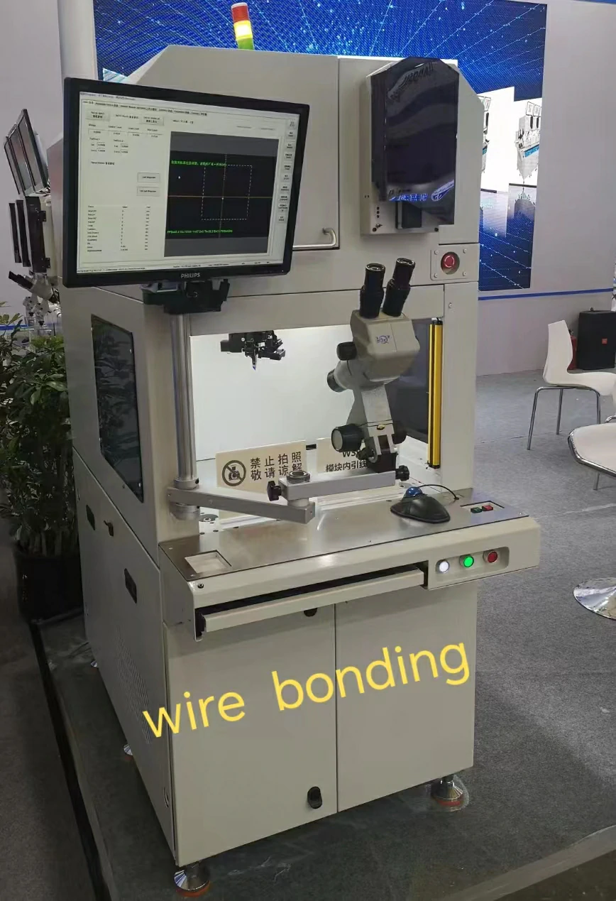
The chip and wire bonding process is a highly automated, multi-step procedure that takes place inside a sophisticated wire bonder. Let's break down the sequence for a typical thermosonic ball bonding cycle, the most common wire bonding technique.
First, the chip (or die) is securely mounted onto a substrate or leadframe. This assembly is then heated to the target temperature. A very thin wire, typically gold or copper, is threaded through a hollow tool called a capillary. An electric spark is fired at the end of the wire, melting it and forming a perfect sphere, known as the free-air ball. This is where the process truly begins.
The machine’s robotic arm then moves the capillary down to the chip. It presses the ball onto a specific bond pad with precise force. Simultaneously, the machine applies a burst of ultrasonic energy. This creates the first bond, a strong, welded connection. The machine then raises the tool and begins to move toward the second connection point on the substrate, paying out the wire as it goes. The path it takes forms a carefully engineered loop in the wire. Finally, the tool presses the wire against the substrate to form the second bond (a "stitch" bond). A clamp grips the wire, and the tool moves upward, breaking the wire at the heel of the second bond and leaving a small wire tail ready for the next cycle. This entire wire bonding process, from the first bond to the wire break, happens in a fraction of a second.
What Materials and Types of Wire are Used in Wire Bonding?
The selection of materials and wire is a critical decision in the wire bonding process. The choice directly impacts the cost, performance, and reliability of the electronic device. The wires for wire bonding must have high electrical conductivity, good mechanical strength, and resistance to corrosion. The three primary types of wire used in wire bonding are gold, copper, and aluminum.
- Gold (Au) Wire: Gold wire is the premium choice. It is extremely reliable because it does not oxidize, ensuring a clean surface for a perfect bond. It is also very soft and ductile, which allows for a strong bond to be formed with relatively low force and temperature. This makes gold wire bonding ideal for delicate, high-density chips. The main drawback of using gold wire is its high cost. A good bond with a gold wire is often the easiest to achieve.
- Copper (Cu) Wire: Copper wire has emerged as a cost-effective alternative to gold. Its electrical and thermal conductivity are even better than gold's. However, copper wire bonding presents more challenges. Copper is harder than gold, so the bonding parameters must be carefully controlled to avoid damaging the chip. It also oxidizes readily, which can interfere with the bond. This requires the bonding to be done in an inert atmosphere. Despite these challenges, its low cost makes it a popular choice.
- Aluminum (Al) Wire: Aluminum wire is the workhorse of the power electronics industry. It is typically used in wedge bonding applications. When an aluminum wire is bonded to the aluminum bond pad on a chip, it creates a highly reliable mono-metallic system. This avoids the formation of brittle intermetallic compounds that can occur in gold wire bond-bond pad metal systems, especially at high temperatures. An aluminum wire is also very cost-effective. We specialize in providing high-purity pure aluminum wire for these demanding applications.
Why is Gold Wire So Prevalent in Bonding Processes?
Despite its high cost, gold wire has remained a cornerstone of high-reliability chip packaging for several key reasons. Its prevalence in bonding processes is a testament to its exceptional material properties, which make forming a consistent and reliable bond easier than with other materials. For an engineer tasked with ensuring maximum yield and long-term device performance, the advantages of a gold wire bond are often compelling.
The most significant advantage of gold wire is its chemical inertness. Gold does not rust or oxidize under normal atmospheric conditions. This means the surface of the wire is always pristine and ready for bonding, eliminating a major variable that can cause poor bond quality and manufacturing defects. This is in stark contrast to copper, which requires a protective atmosphere to prevent oxidation from interfering with the bond. The bonding of gold is simply more forgiving.
Furthermore, gold wire is very ductile and soft. This allows for excellent bond formation and bond quality at lower forces and temperatures during thermosonic bonding. Using less force reduces the risk of cracking or damaging the fragile silicon chip beneath the bond pad. The softness of the gold wire allows it to deform easily, creating a large, reliable contact area for the bond. While avoiding gold wire bonds may be a goal for cost reduction, for mission-critical applications where failure is not an option, the reliability offered by a gold wire bond is often worth the premium price.
How is Wedge Bonding Different from Other Bonding Technologies?
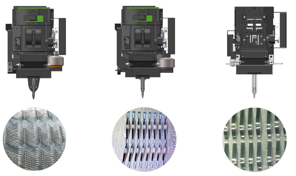
Wedge bonding stands out among wire bonding technologies due to its unique tool, process flow, and applications. Unlike ball bonding, which uses a round capillary and starts with a ball-shaped bond, wedge bonding uses a wedge-shaped tool to press the wire directly against the bonding surface. The wire is directly pressed and scrubbed with ultrasonic energy to form a stitch-like bond. This fundamental difference leads to several distinct characteristics.
One key feature of wedge bonding is its ability to create a very low-profile bond. The resulting stitch bond is much flatter than a ball bond, making wedge bonding ideal for applications where vertical clearance is limited. It also allows for extremely fine-pitch bonding, where the bond pads on a chip are placed very close together. The wedge bonding process provides excellent control over the loop profile of the wire, which is critical in high-frequency devices. This precision is why we engineer tools like our customized wedge bonding tool to meet the tightest tolerances.
Wedge bonding is the dominant technique for aluminum wire bonding. The ultrasonic scrubbing action is highly effective at breaking through the native oxide layer on an aluminum wire. This process can also use gold wire (gold wedge bonding) or ribbon, making it very versatile. However, wedge bonding is generally slower than ball bonding because the tool must be aligned for each bond. Despite this, for high-power devices and fine-pitch applications, the reliability and precision of the wedge bond make it the superior choice among different bonding technologies. The wedge bonding bond is a workhorse.
What Constitutes a "Good" Bond and How Do You Achieve It?
A "good" bond is one that is both electrically sound and mechanically robust, capable of lasting the entire lifetime of the electronic device. For an engineer, a good bond is defined by specific, measurable criteria: sufficient bond strength, low electrical resistance, and a consistent, well-formed shape. Achieving this perfect bond is the primary goal of optimizing the wire bonding process.
Visually, a good ball bond should be perfectly round and centered on the bond pad, with visible deformation (squash) indicating a solid metallurgical connection. A good wedge bond should show a distinct, uniform impression from the bonding tool. There should be no cracks in the bond or the surrounding chip, and the wire exiting the bond (the ball bond neck or heel) should be free from excessive thinning or damage. The integrity of the wire bond-bond pad interface is paramount.
Achieving a good bond requires meticulous control over the bonding parameters: force, ultrasonic power, time, and temperature. These must be tailored to the specific materials and wire being used, including the wire size and the metallization of the bond pad. High-quality tools are non-negotiable; a worn or poorly made tool cannot produce a consistent bond. Finally, cleanliness is critical. Any contamination on the chip or wire can prevent a proper bond from forming. Reliable bonding is the result of a well-designed process, superior materials, and continuous monitoring. A strong bond is a reliable bond. Every single bond matters.
What is Involved in the Testing of Wire Bonds for Reliability?
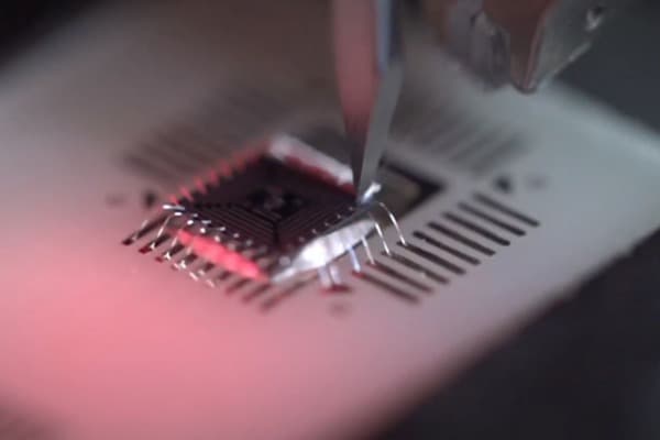
Ensuring wire bond reliability is a critical part of the quality control process in semiconductor manufacturing. A beautiful-looking bond is meaningless if it doesn't have the required strength. Therefore, rigorous testing of wire bonds is performed to validate the bonding process and guarantee long-term performance. The two most common destructive tests are the wire pull test and the bond shear test.
Wire pull testing is the quintessential test for any wire bond. It involves using a small hook to pull upward on the wire at the apex of its loop until either the wire breaks or one of the bonds lifts off. The force required to cause this failure is measured in grams-force. This data is then compared against industry standards (like MIL-STD-883) to determine if the bond strength is acceptable. The location of the failure is also recorded, as it provides valuable diagnostic information about the health of the wire bond and the overall bonding process.
Bond pull and shear testing provides another layer of validation. A bond shear test is used to directly measure the adhesion of the bond to the bond pad. A tool comes in from the side and pushes against the bond (the ball bond or wedge bond) until it shears off. The force required to shear the bond is a direct measure of the quality of the metallurgical weld. Both wire bond pull and shear tests are typically performed on a sample basis to monitor the stability of the bonding processes. This constant testing of wire ensures that every electronic device that leaves the factory has a robust and reliable wire bond network.
What are the Common Causes of Wire Bond Failures and How Can They Be Avoided?
Wire bond failures are a major concern in electronics manufacturing, as they can lead to device malfunction and costly recalls. These failures can generally be traced back to issues in one of three areas: materials, process control, or post-bonding stress. Understanding these root causes is the first step toward prevention. A failed wire bond is a failed bond.
One of the most common causes of a weak bond is contamination. Any foreign material on the bond pad or the wire—such as oxides, dust, or chemical residues—can act as a barrier, preventing a strong metallurgical bond from forming. This highlights the need for stringent cleanroom protocols. Another major issue is improper bonding parameters. Too much force can crack the chip, while too little force or ultrasonic energy can result in a non-stick, or lifted, bond. The process window for a good bond can be narrow, requiring precise machine calibration. This is where the expertise of a supplier like Dongxin Electronic Technology becomes invaluable.
Failures can also occur after the wire bond is made. Brittle intermetallic compounds, especially in gold-aluminum bond systems, can grow over time and lead to a weak bond. Mechanical stress from the device's packaging material during thermal cycling can also cause fatigue in the wire, leading to a break at the heel of the bond. Avoiding these wire bond failures requires a holistic approach: using high-quality materials, meticulously controlling the bonding process, designing for mechanical stress, and performing rigorous reliability testing. Every bond in the electronic device must be perfect.
Key Takeaways
- The Wire Bond is Critical: The wire bond is the fundamental connection that enables a semiconductor chip to function within an electronic device. Each bond is a vital link.
- Not the Same as Solder: A wire bond is a precise, solid-state weld, whereas solder is a metallic glue. The bond is much stronger and smaller.
- Three Core Processes: Bonding processes like thermosonic, ultrasonic, and thermocompression are used, with thermosonic bonding being the most common for its balance of speed and safety for the chip.
- Material Matters: The choice between gold wire, copper wire, and aluminum wire is a trade-off between cost, performance, and the specific application needs. A suitable wire is key to a good bond.
- Quality is Measurable: A good bond has high bond strength and low electrical resistance. This is validated through destructive tests like wire pull and bond shear testing.
- Failure is Preventable: Most wire bond failures stem from contamination, incorrect bonding parameters, or mechanical stress. A robust process and high-quality materials are the best prevention. The goal is a perfect bond, every time.