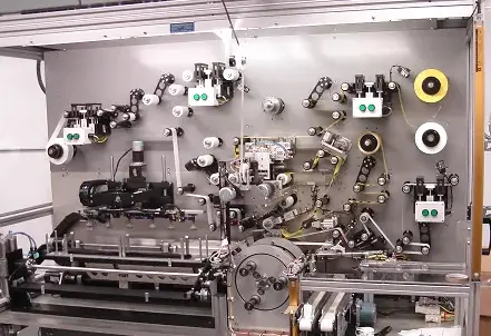
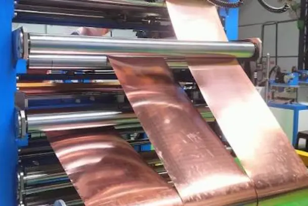
Foil winding in transformers is a winding method that uses wide, thin strips of copper or aluminum foil instead of round or rectangular winding wire. Each foil layer is separated by insulation material and wound around the transformer core or coil former to create a low-voltage or high-current winding.
Foil winding is commonly used where a transformer requires high current-carrying capability, compact winding geometry, controlled temperature distribution, and suitable short-circuit performance. It is often applied to low-voltage windings in distribution transformers, dry-type transformers, power transformers, reactors, and selected industrial electrical equipment.
How Does Foil Winding Work?
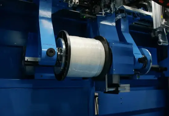
A foil winding uses a continuous strip of conductive foil as the winding conductor. The foil is fed from a coil, aligned, insulated, and wound layer by layer under controlled tension.
Each layer acts as one or more turns, depending on the transformer design. Insulation material is placed between foil layers to provide the required electrical separation. The finished winding is then connected to leads, terminals, or busbar systems according to the transformer’s electrical design.
The foil winding process requires control of:
- Foil width and thickness
- Copper or aluminum material selection
- Winding tension
- Layer insulation type and thickness
- Edge alignment
- Turn count
- Lead and terminal connection
- Cooling-channel arrangement
- Winding dimensions and concentricity
Accurate control is important because winding quality affects electrical performance, insulation reliability, thermal behavior, and mechanical stability.
Foil Winding vs. Wire Winding
Traditional transformer windings are often made from round magnet wire or rectangular conductor. Foil winding uses a broad strip conductor instead.
| Feature |
Foil Winding |
Wire Winding |
| Conductor form |
Wide copper or aluminum foil |
Round or rectangular wire |
| Typical application |
Low-voltage, high-current windings |
Higher-voltage or multi-turn windings |
| Current path |
Broad conductor width |
Individual conductor cross-section |
| Layer structure |
Foil layer with insulation between layers |
Multiple wire turns and layers |
| Design flexibility |
Effective for selected compact, high-current designs |
Effective for a wide range of voltage and turn requirements |
| Selection basis |
Current, voltage, insulation, thermal and mechanical requirements |
Current, voltage, insulation, geometry and manufacturing requirements |
Neither approach is universally better. The correct choice depends on the transformer rating, voltage level, current, operating frequency, insulation requirement, cooling method, manufacturing process, and applicable standards.
Why Is Foil Winding Used in Transformers?
Foil winding can provide several practical benefits when it is properly designed and manufactured.
High Current-Carrying Capability
The wide cross-section of a foil conductor can be well suited to low-voltage, high-current transformer windings. The conductor dimensions can be selected to achieve the required current density and resistance.
Balanced Temperature Distribution
A foil winding can help create a more even temperature profile across the conductor width when the winding design, insulation system, cooling method, and operating load are correctly matched.
Compact Winding Construction
Foil conductors can make efficient use of available winding space in suitable designs. This may support compact transformer construction while maintaining the required electrical clearances and insulation.
Short-Circuit Performance
Transformer windings are exposed to electromechanical forces during fault conditions. A well-engineered foil winding can offer favorable mechanical characteristics in selected low-voltage transformer designs. However, short-circuit withstand capability must always be evaluated through the complete winding structure, supports, insulation system, clamping arrangement, and transformer design.
Manufacturing Consistency
Automated foil winding equipment can support consistent foil alignment, insulation placement, tension control, and turn counting. This can improve repeatability when manufacturing parameters are properly managed.
Copper Foil vs. Aluminum Foil Winding
Copper and aluminum are both used for transformer foil winding. The selection depends on electrical, mechanical, thermal, supply, cost, and manufacturing considerations.
Copper Foil Winding
Copper has high electrical conductivity and can provide a smaller conductor cross-section for the same current requirement compared with aluminum. It is often selected where compact dimensions, lower conductor resistance, and specific connection requirements are important.
Aluminum Foil Winding
Aluminum is lighter and may offer material-cost advantages in some designs. Because aluminum has lower electrical conductivity than copper, the conductor dimensions must be adjusted appropriately to achieve the required electrical performance.
The material should be chosen according to the complete transformer specification rather than material price alone.
Common Applications of Transformer Foil Winding
Foil winding is used in various electrical products, particularly where low voltage and high current are involved.
Typical applications include:
- Distribution transformers
- Dry-type transformers
- Cast-resin transformers
- Low-voltage power transformers
- Industrial control transformers
- Rectifier transformers
- Welding transformers
- Renewable-energy electrical systems
- Reactors and inductive components
- Power-electronics transformer applications
The final application determines the required conductor material, foil dimensions, insulation system, cooling arrangement, and testing requirements.
Key Design Considerations for Foil Winding
A successful foil winding design requires more than selecting foil width and thickness. Engineers and buyers should consider the following factors.
Voltage and Current Rating
The winding must be designed for the required voltage, current, turns ratio, insulation level, and operating duty. Foil winding is often suitable for low-voltage, high-current sections, but the final arrangement depends on the entire transformer design.
Foil Width and Thickness
Foil dimensions influence current density, resistance, winding build, heat dissipation, and mechanical behavior. The dimensions should be calculated for the intended operating conditions.
Insulation System
Insulation between foil layers is essential. The insulation material, thickness, thermal class, dielectric strength, and edge coverage must match the voltage and environmental requirements.
Cooling and Temperature Rise
Transformer thermal performance depends on conductor losses, core losses, airflow or oil circulation, winding arrangement, cooling channels, enclosure design, and ambient temperature. Foil winding should be designed as part of the complete thermal system.
Mechanical Strength
The coil structure must withstand normal handling, transport, vibration, and fault-related forces. Winding tension, clamping, insulation bonding, supports, and coil geometry all affect mechanical performance.
Termination Design
Foil conductors require suitable connection methods to terminals or leads. The connection area must be designed to manage current, contact quality, heat generation, and material compatibility.
Foil Winding Manufacturing Quality Checklist
When sourcing a transformer foil winding solution, confirm the following points:
- Copper or aluminum foil grade
- Foil thickness and width tolerance
- Insulation material and thermal class
- Edge alignment control
- Winding tension control
- Turn-count accuracy
- Layer-to-layer insulation coverage
- Lead and terminal connection method
- Coil dimensional tolerance
- Short-circuit design requirements
- Electrical testing requirements
- Traceability and inspection records
These checks help buyers evaluate whether the foil winding process is aligned with the required transformer performance and production consistency.
Conclusion
Foil winding is a transformer winding method that uses copper or aluminum foil strips with insulation between layers. It is commonly used for suitable low-voltage and high-current transformer windings because it can support compact construction, controlled thermal performance, and robust electrical design.
The right foil winding solution depends on the transformer’s voltage, current, insulation level, cooling method, mechanical requirements, material choice, and applicable standards. A qualified design and controlled manufacturing process are essential for dependable transformer performance.
For foil winding equipment and transformer winding support, please contact us: https://www.dgdx-elec.com/contact-us/
FAQ
What is foil winding in a transformer?
Foil winding is a transformer-coil construction method that uses wide copper or aluminum foil strips separated by insulation layers instead of traditional winding wire.
Why is foil winding used for low-voltage transformer windings?
Foil winding can be suitable for low-voltage, high-current windings because the conductor width and cross-section can be designed to carry high current while supporting compact coil construction.
Is copper foil better than aluminum foil for transformer winding?
Neither material is automatically better. Copper and aluminum should be selected based on electrical requirements, conductor size, thermal performance, mechanical design, manufacturing needs, availability, and project cost.
Can foil winding improve short-circuit performance?
A properly engineered foil winding can support favorable short-circuit performance in selected transformer designs. The complete coil structure, insulation, supports, clamping, and transformer design must still be evaluated.
What should I check when selecting a foil winding solution?
Confirm the foil material, dimensions, insulation system, winding accuracy, thermal class, cooling requirements, terminal design, testing requirements, and compatibility with the transformer specification.